As a supplier of 24V linear actuators, I often receive inquiries from customers about how to connect these actuators to a Programmable Logic Controller (PLC). In this blog post, I'll provide a detailed guide on the process, ensuring that you can make a successful connection and optimize the performance of your system.

Understanding the Basics
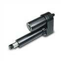
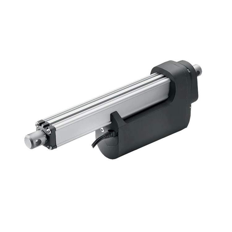
Before we delve into the connection process, it's essential to understand the key components involved. A 24V linear actuator is a device that converts electrical energy into linear motion. It typically consists of a motor, a gearbox, and a lead screw or a belt drive. On the other hand, a PLC is a digital computer used for automation of industrial processes, such as controlling machinery on factory assembly lines.
Selecting the Right Actuator
When it comes to choosing a 24V linear actuator for your application, several factors need to be considered. First, determine the required force and stroke length. The force is the amount of push or pull the actuator needs to generate, while the stroke length is the distance the actuator can extend or retract. Additionally, consider the speed of the actuator. If you need a fast - moving system, you might want to check out our High Speed Linear Actuator. For heavy - duty applications, our Heavy Duty Linear Actuator would be a great choice. And if you prefer an electric - powered option, our Electric Linear Actuator is worth considering.
Safety First
Before starting any electrical work, safety should be your top priority. Make sure the power supply to the PLC and the actuator is turned off. Wear appropriate safety gear, such as insulated gloves and safety glasses. Also, ensure that the work area is clean and dry to prevent any electrical hazards.
Step - by - Step Connection Guide
Step 1: Gather the Necessary Tools
You will need a few tools for this process, including wire strippers, crimping tools, a multimeter, and electrical tape. These tools will help you make proper electrical connections and test the system.
Step 2: Identify the Actuator Wires
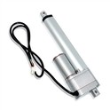
Most 24V linear actuators have at least two wires: a positive (+) and a negative (-) wire. The positive wire is usually red, and the negative wire is black. However, it's always a good idea to refer to the actuator's manual to confirm the wire colors and functions.
Step 3: Prepare the PLC Outputs
The PLC has output modules that can be used to control the actuator. Determine which output points you will use for the actuator control. The output points should be capable of providing a 24V DC signal. Check the PLC's manual for the proper configuration of the output modules.
Step 4: Make the Electrical Connections
- Power Supply: Connect the 24V DC power supply to the actuator. Connect the positive terminal of the power supply to the positive wire of the actuator and the negative terminal to the negative wire.
- PLC Connection: Connect the output signals from the PLC to the actuator. You can use a relay module to isolate the PLC from the actuator's high - current circuit. Connect the output signal from the PLC to the coil of the relay. Then, connect the contacts of the relay to the actuator's power wires. For example, if the PLC output goes high, it energizes the relay coil, and the relay contacts close, allowing power to flow to the actuator.
Step 5: Grounding
Proper grounding is crucial for the safety and stability of the system. Connect the ground wire of the actuator and the PLC to a common ground point. This helps to prevent electrical noise and reduces the risk of electrical shock.
Step 6: Testing the Connection
After making all the connections, turn on the power supply to the PLC and the actuator. Use a multimeter to check the voltage at the actuator's terminals. If the voltage is correct, you can start testing the actuator's movement. Send a control signal from the PLC to the actuator and observe if the actuator extends or retracts as expected. If there are any issues, double - check all the connections and the PLC programming.
Troubleshooting
If the actuator doesn't work as expected, here are some common issues and solutions:
- No Movement: Check the power supply to the actuator. Make sure the voltage is within the specified range. Also, check the connections to the actuator and the PLC. A loose connection can prevent the actuator from receiving power.
- Erratic Movement: This could be due to electrical noise or incorrect PLC programming. Check the grounding of the system and make sure the PLC program is correctly configured. You can also use shielding cables to reduce electrical interference.
Optimizing the System
Once the connection is successful, you can optimize the system for better performance. You can adjust the speed and force of the actuator by modifying the PLC program. For example, you can use pulse - width modulation (PWM) techniques to control the speed of the actuator.
Conclusion
Connecting a 24V linear actuator to a PLC is a relatively straightforward process if you follow the steps outlined in this guide. By understanding the components, ensuring safety, and making proper connections, you can create a reliable and efficient automation system. If you have any further questions or need assistance with selecting the right actuator for your application, please don't hesitate to contact us. We are always ready to help you with your procurement needs and discuss how our products can best fit your requirements.
References
- "Industrial Automation Handbook"
- Actuator Manufacturer's Manuals
- PLC Manufacturer's Manuals